Problem Statement
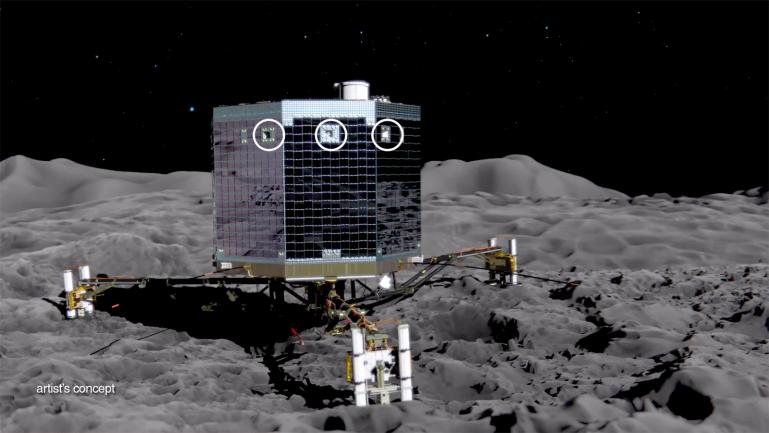
Space missions to the micro-gravity environment of a comet or asteroid are a relatively new desire from private companies and space agencies. The only mission attempting to land a probe on a comet or asteroid so far has been the Rosetta mission with its Philae lander. The mission resulted in a failure of the lander’s anchoring system. In addition, there are few other developed concepts exploring a method of anchoring a spacecraft to an asteroid or comet. Team Talus investigated a solution to the problem of anchoring a spacecraft in a low-g environment and produced a prototype demonstrating the ability to provide an anchoring force between a lander and a simulated asteroid or comet surface.
This project was part of the Purdue senior design course that took place from January to May 2016. The given budget was $400.
Major Contributions
Control systems algorithms (LabVIEW with myRIO)
Part drawings and manufacturing
Machining of structure components
Test rig construction
Logo design

Subsystems
The sections below describe each subsystem in more detail, but you should check out the final report above to learn more about our methods and conclusions!
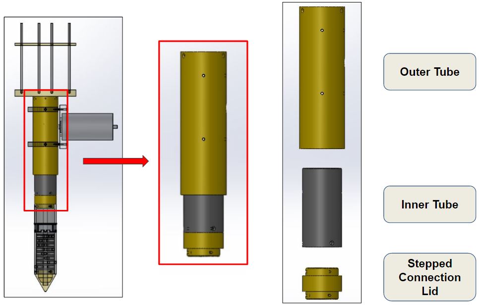
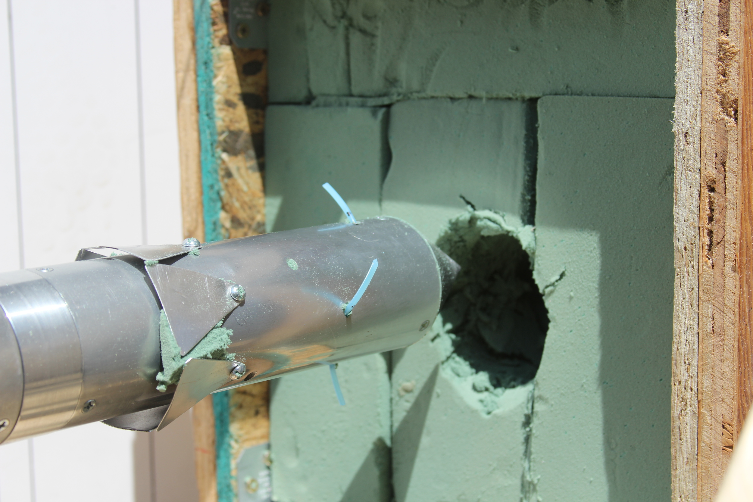
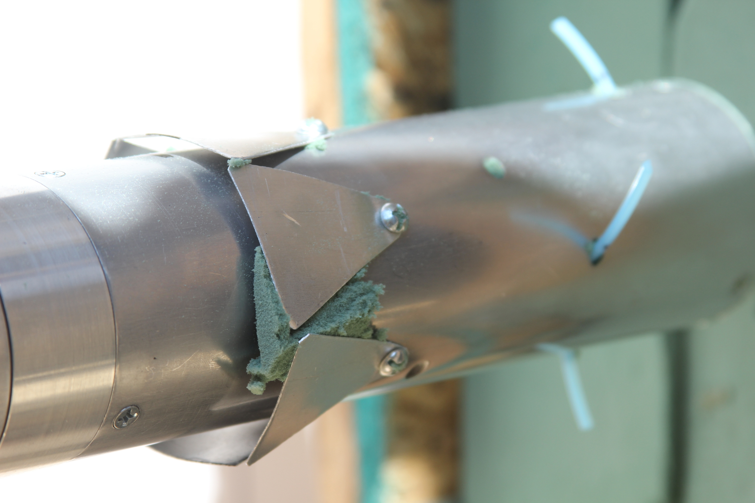
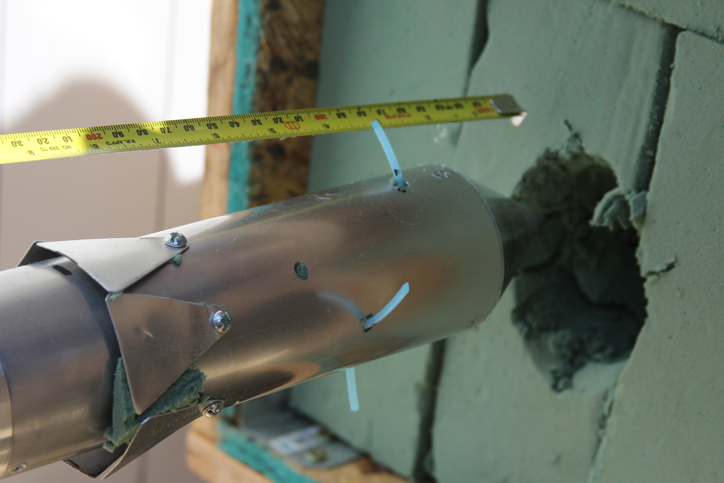
1 Penetration
Aluminum cylinder perforated for root deployment
Conical shaped leading edge for minimal penetration resistance
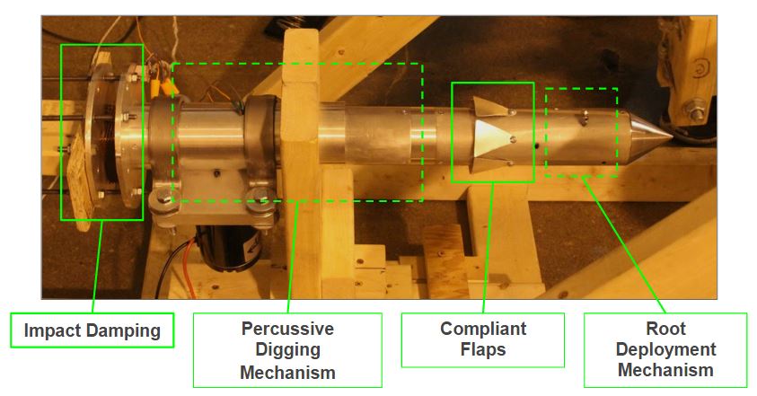
Compliant flaps increase the force required to pull the anchor from the syrface


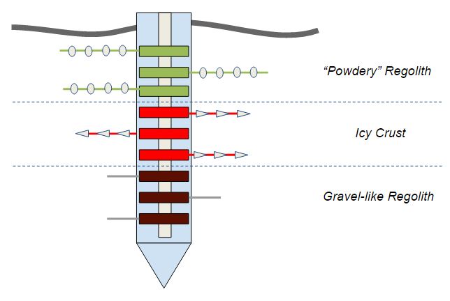
2 Roots
Horizontally acting root deployment via center shaft powered by DC motor
Flexible braided wire roots stored in coils inside the root casing are easy to ship, replace, and customize for various landing surfaces
Using horizontally acting roots widens the effective area of the regolith column underground, increasing anchoring force


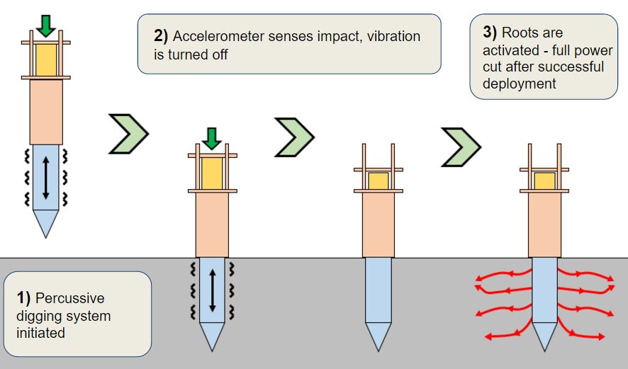
3 Percussive Digging
45-85 Hz operating frequency
Reduces required surface penetration force by 15 times by reducing static friction on the anchor casing outer surfaces
Slider-crank vibration mechanism consisting of crank, follower arm, and inner structure tube as "slider"


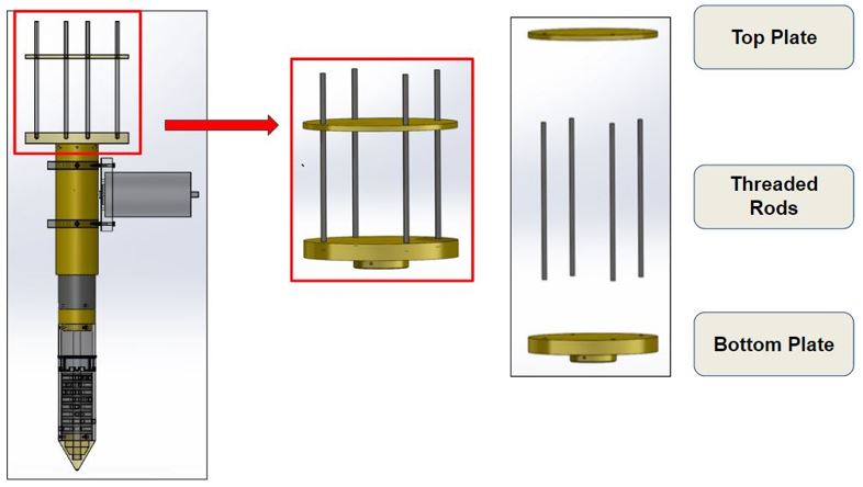
4 Damping Systems and Regolith Simulant
Damping system designed to dissipate 24 kJ/kg of landing energy
Anchoring system attaches to spacecraft via top plate
Nomex crushable honeycomb damping material seated between top and bottom plates
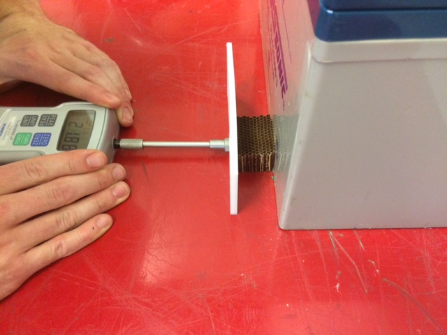
Regolith simulant is phenolic foam (wet floral foam) with a comparable compressive strength of 62.5 kPa
Material properties of damping material and regolith simulant obtained through manual compressive strength tests


5 Structures and Control Systems
Root deployment controlled with accelerometer - deployment is triggered by acceleration limits
MyRIO microcontroller + LABVIEW system design platform used to develop control alogorithm
Stepped aluminum connection joints provide flush outer anchor surface
Damping system effectiveness was measured by comparing the acceleration spikes of the two onboard accelerometers