
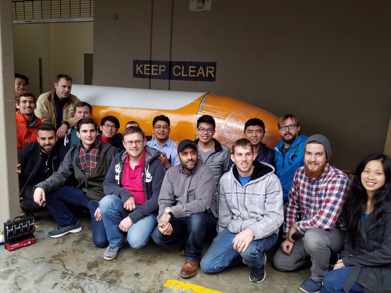
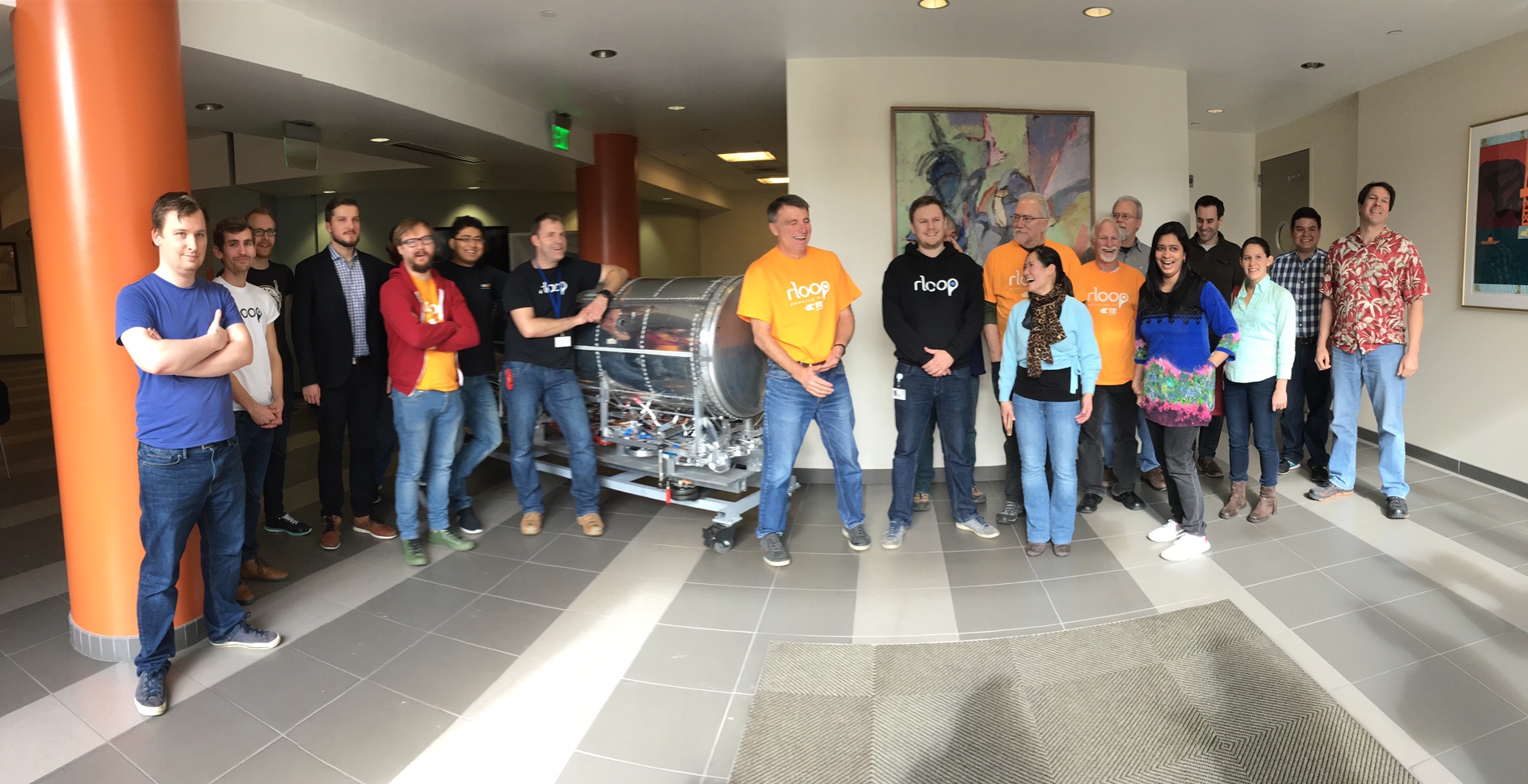
rLoop is a non-profit, open-source, online community of individuals from various disciplines all over of the world. The common mission of everyone on this team is to revolutionize transportation - starting with the Hyperloop.
The team was formed on Reddit in 2015 when SpaceX announced the first Hyperloop Pod Competition. The team has since grown to over 100 members. While I'm not currently active with this team, I am still super impressed with their efforts and am excited to see what they accomplish. See what they're up to by visiting their website, here!
Major Contributions
- Auxiliary propulsion mechanical design
- Timing belt and pulley selection
- Part drawings and manufacturing
- Entire pod wire harness planning and installation
- Torque specifications for critical fastener joints
- Miscellaneous electrical component assembly and installation
Project Summary
rLoop participated in SpaceX's very first Hyperloop Pod Competition in 2017 to test and validate the unique communication and management structure that the team utilizes to manage engineering projects. rLoop was the only non-university team to advance to the finals out of over 100 teams total and went on to receive the "Pod Innovation Award". This competition required the careful design and build of a hypothetical Hyperloop pod that was tested on SpaceX's test track in Hawthorne, CA. Take a look at the media at the bottom of the page for a more in-depth look at rLoop's pod design and our story.
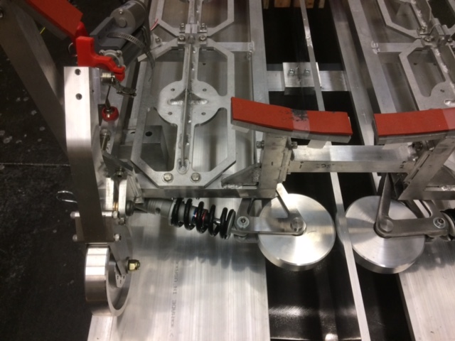
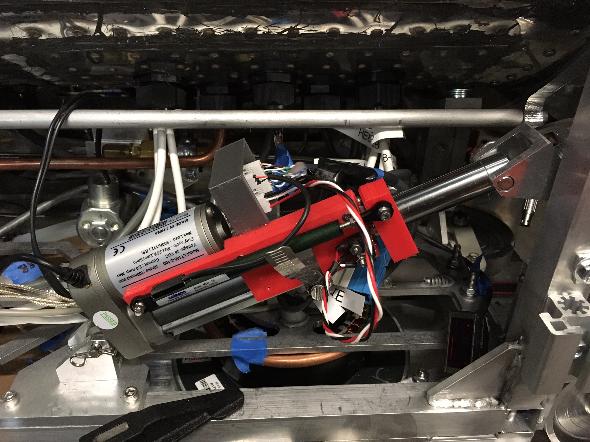
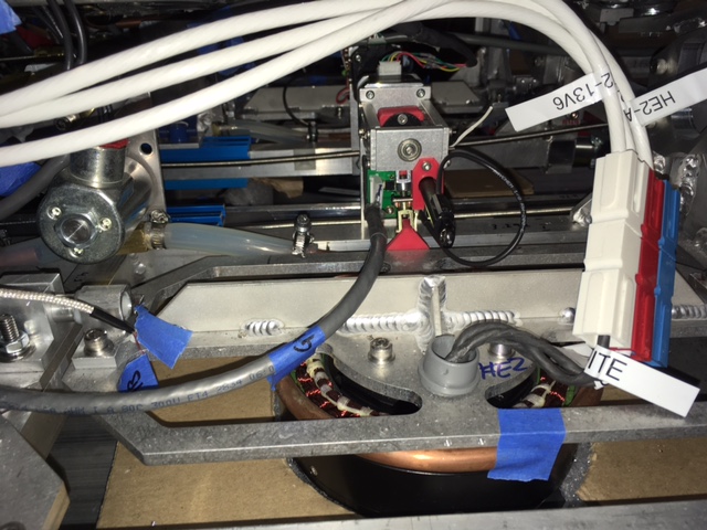
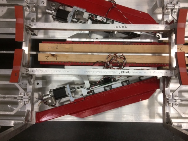

Auxiliary Propulsion
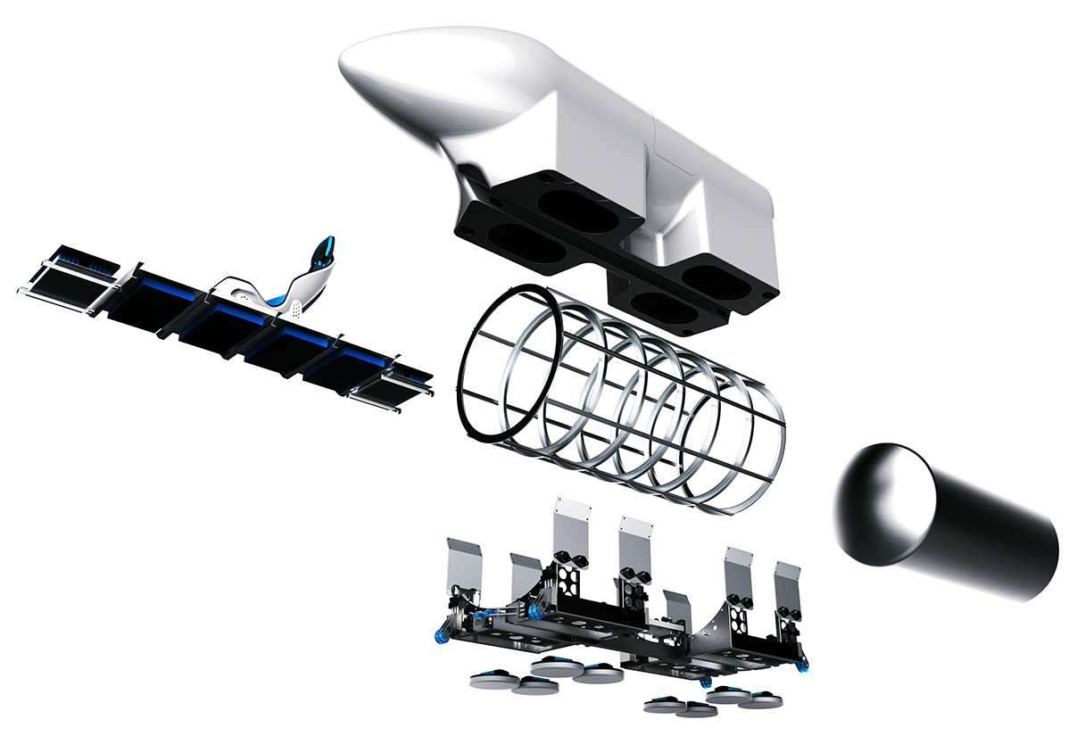
Auxiliary Propulsion System
The auxiliary propulsion system performs three major functions:
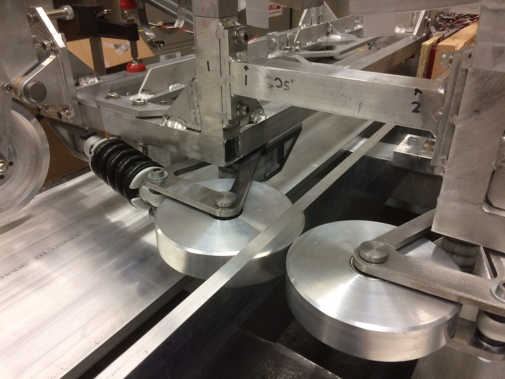
- Provide low speed transportation (clutch/motor engaged)
- Elevate pod substructure until levitation is achieved by hover engines (clutch/motor disengaged)
- Stow away during high speed transportation
Composed of a brushless DC servo motor, timing belts and pulleys, a re-purposed Ford F-150 AC air compressor clutch, and an electrical linear actuator, this mechanism was, in the end, designed by more than 10 domestic and international professionals with variable experience levels and technical disciplines.
Actuator Selection
For this design project I was responsible for the selection of the actuator used to raise and lower the wheel and assisted in the design of the motor drive system. To understand the range of motion required by the linear actuator I performed a motion study using a point path analysis in Matlab. By solving two vector loops simultaneously this analysis output the angular displacement of the actuator, to check for interference with other onboard systems, and the stroke length required by the actuator to move the landing gear wheel from one vertical extreme to another (wheels down to wheels up). Multiple chassis mounting locations for the actuator were iterated to optimize mechanical advantage and to generate a stroke length that matched closely with COS actuators.
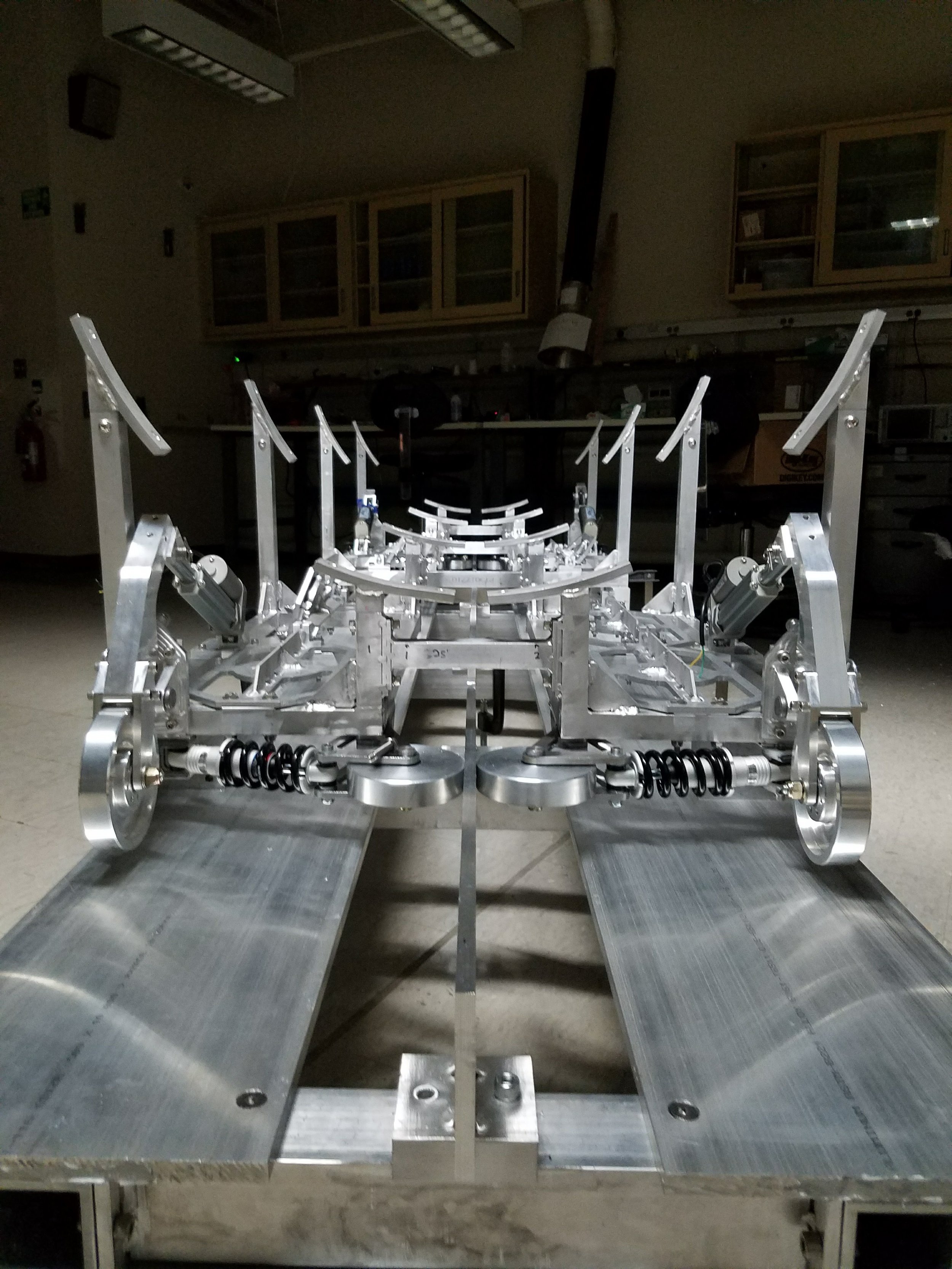
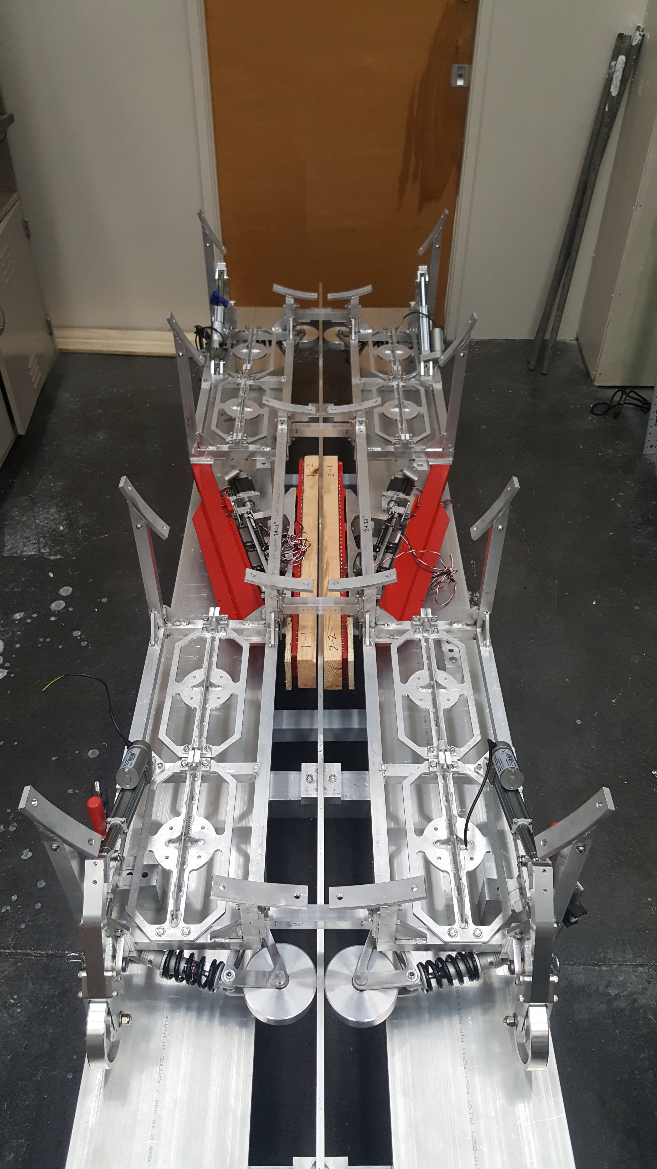
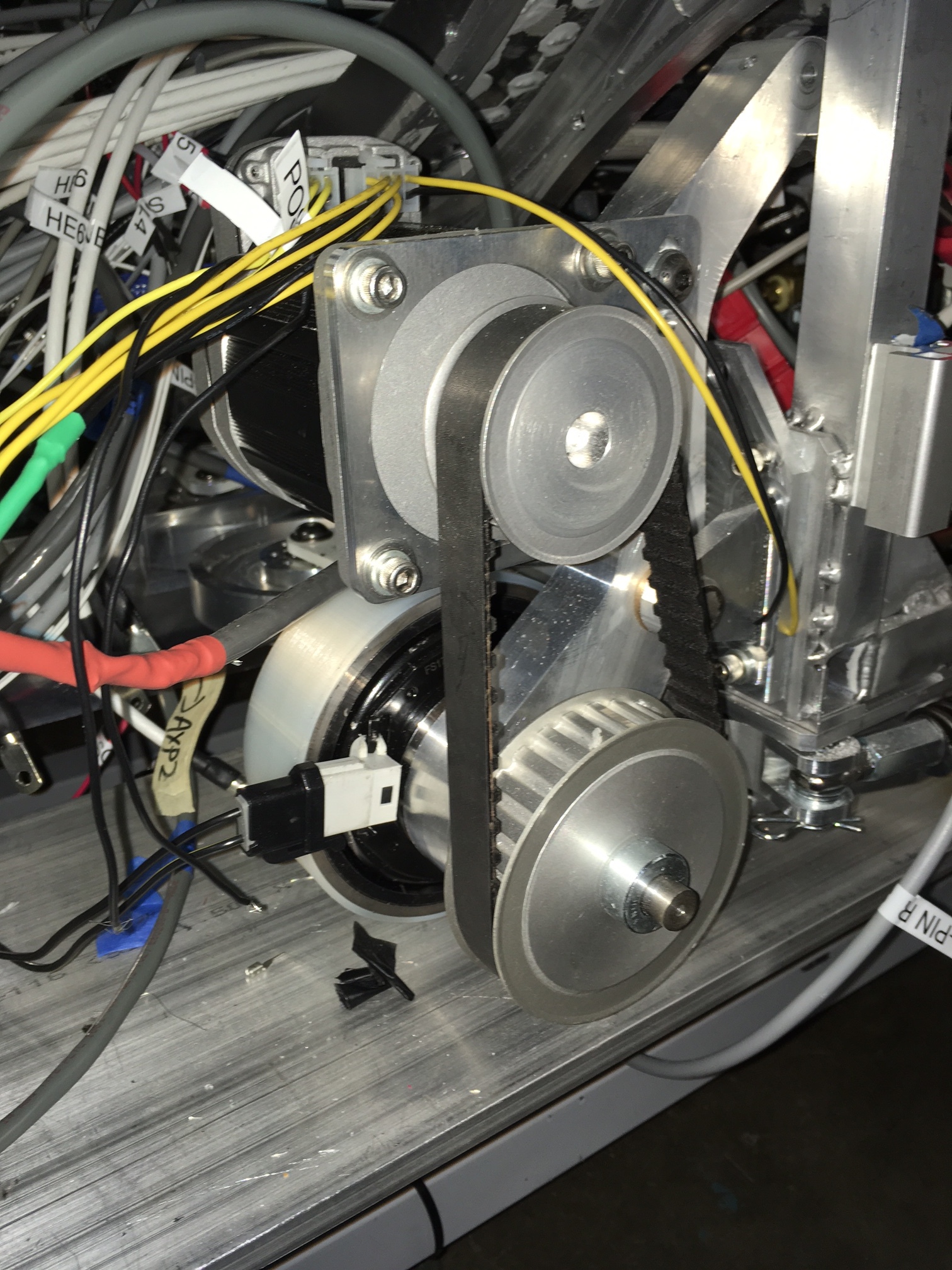
Motor Selection
A Teknic 72V brushless DC motor was selected for this motor drive design because of its comparability with the pod's batteries and its featured integrated controller (our embedded systems team loved this). The motor was mounted above the wheel and connected via timing belts and pulleys, shown in the "Auxiliary Propulsion System" image above. I performed the calculations for pulley ratio and belt sizing based on the torque required by each wheel to move the pod and the motor's performance curve. The calculations where then uploaded to the team's JIRA page for approval from other team members.
Point Path Analysis: Vector Loops
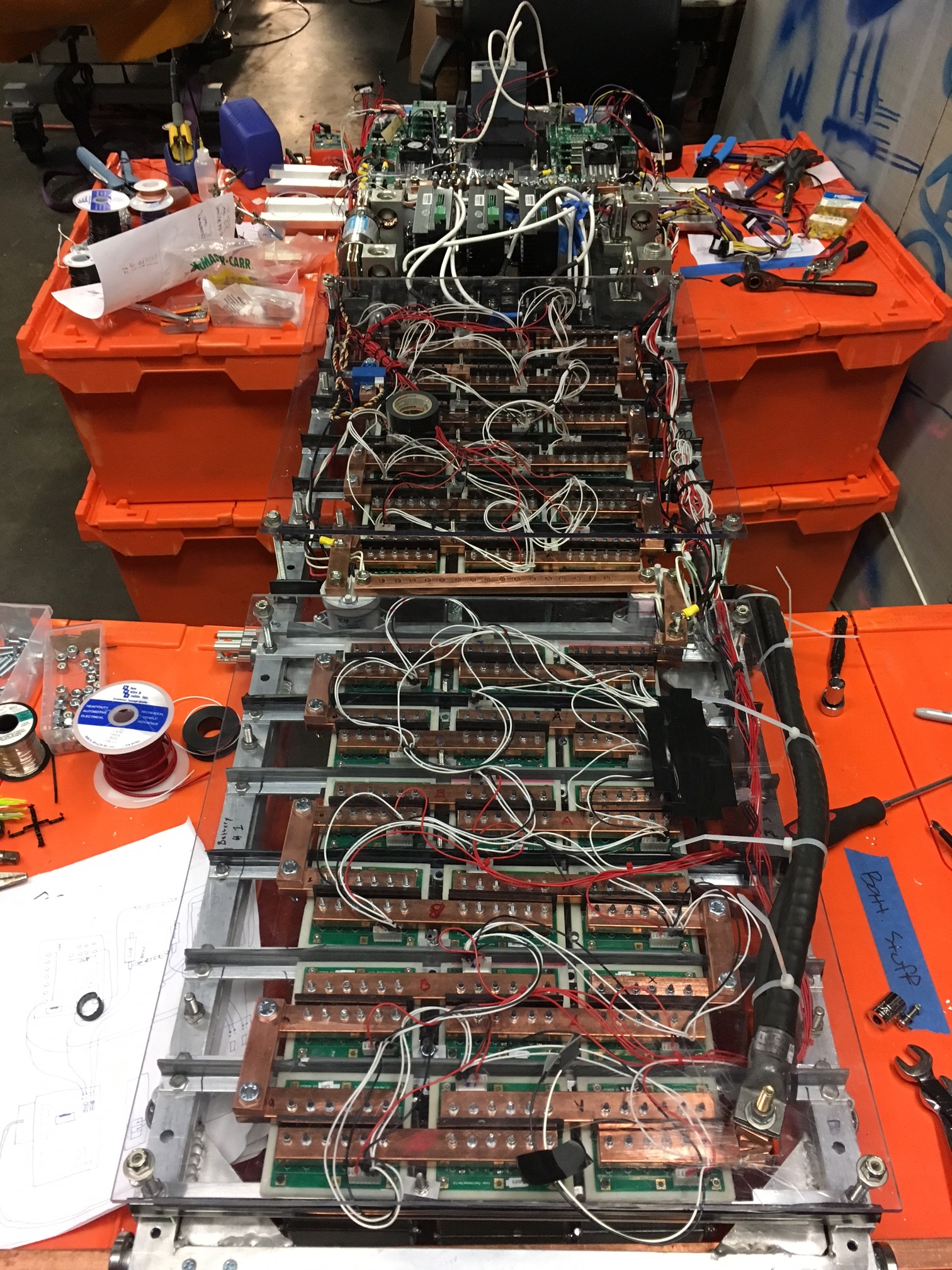
Wiring Harness
Three weeks before competition weekend, I was assigned the task of planning and installing the wiring harness for the entire pod after it became clear that nobody else had been thinking about it. I had no experience with wiring harnesses before this project.
This project had the following objectives:
- Strategically select and route appropriate wires/cables per application with readily available materials
- Create a wire naming convention which specifies any attributes that could be relevant to a technician or de-bugger
- Ensure isolation of power and signal wires when routing to avoid any extraneous noise
- Don't make it look like I've never done this before
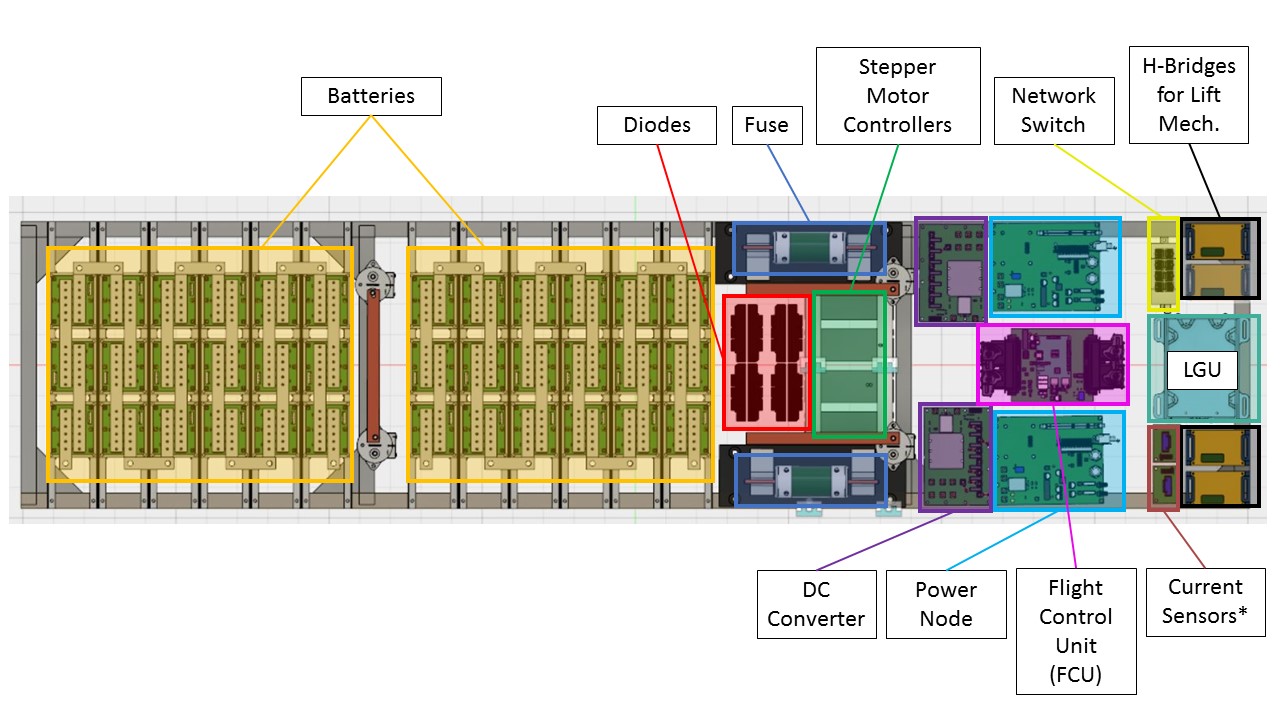
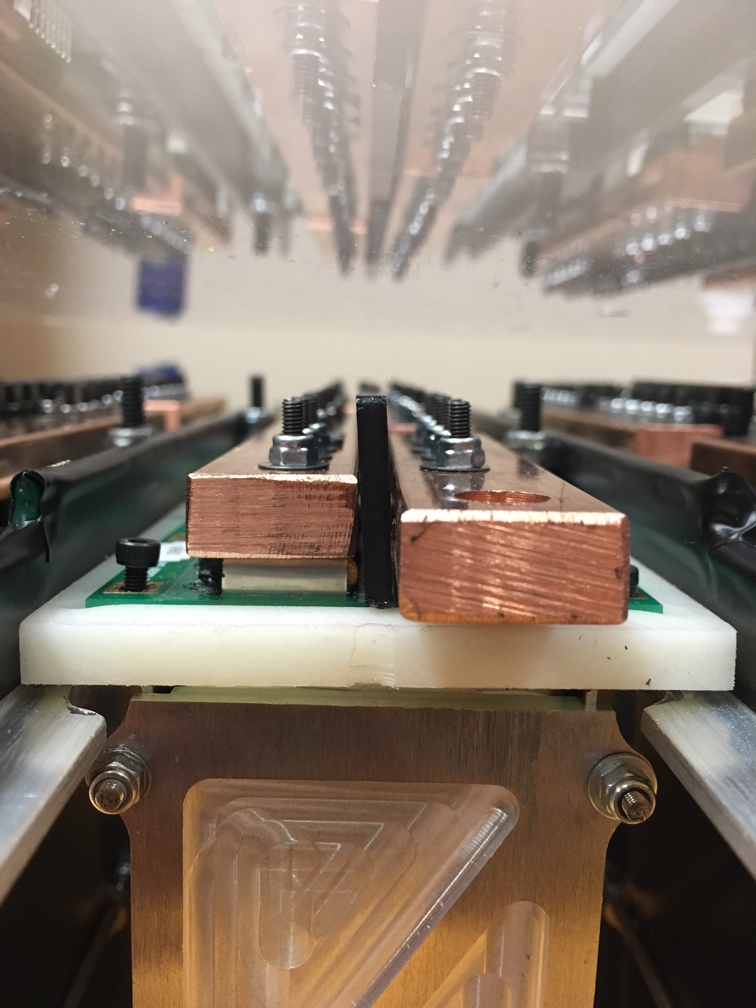
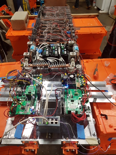
rPod Wiring Harness
Penetration Map with Wire Assignments
Wire Naming Convention
I firmly believe that organization is instrumental in the successful execution of any project. For this one specifically, I utilized organization by creating a map of each penetration in the pressure vessel that specifies which piece of hardware the wire passing through it belongs to, the nature of its signal (e.g. P for power, T for temperature), and how many wires pass through it. The layout matches the orientation seen on the pressure vessel itself (if you look really hard at the picture above you can kind of see what I'm talking about).
This map became a tool to be used by any team member familiar with the pod for any wiring related purposes. It is also directly related to a Google Sheets page that lists each wire and its associated properties.
If I could do things differently, I would start by making everything more organized. Here's how:
- Establish universal wire naming conventions that are easier to understand by anyone unfamiliar with wiring. This is particularly useful in the case of rLoop, where individuals from multiple disciplines may be required to familiarize themselves with this project very quickly.
- Agree on a centralized location for all documentation related to wiring. This includes combining multiple spreadsheets into one, using only Google Drive for storage, etc.
- Provide detailed descriptions for wire color conventions, pin out mapping, technical capabilities of each wire, and the load endured by each wire.
- Use wire that is appropriately sized for each application instead of using only what's on hand. Many wires were over-sized (NEVER under-sized) in this application, adding more weight and inflexibility to the harness.
Torque Specification Chart
The torque specification chart that I developed served to ensure that critical impermanent joints were fastened to proper and safe torque levels. Though specifying torque values for each fastened connection is not always the most accurate or desirable method of ensuring secure and safe joints, for this application it was acceptable.
The design of the flow map on the right serves to direct the assembler to each required joint quickly with the assistance of a clean and straightforward visual aid. The chart assumes familiarity with the pod and its components.
Media
TWiT's bit on rLoop. My interview is at about 28:18.
CBS News SF Bay Area interviews rLoop team leads.